


P&K KFA (VDI 3781 part 4)
Program Description
Contents
1. Introduction
1.1 Overview
1.2 Installation
1.3 Projects
1.4 Integrated help and manual
2. View
2.1 3D View
2.2 Top View / 2D View
3. Input Data
3.1 Background Image / Map
3.2 Buildings)
3.2.1 Add Building
3.2.2 Edit Buildings
3.3 Discharge Devices
3.3.1 Add/Edit Discharge Device
3.3.2 Edit Discharge Devices
3.4 Air Intakes
3.5 Parameter
3.6 CityGML Import
3.7 CityGML Extract
4. Reports
4.1 Graphical Illustration
4.2 Dokumentation of Results
5. Operation
5.1 Within Forms
5.2 Within Tables
1. Introduction
1.1 Overview
With P&K KFA we offer a program to calculate exhaust systems like chimneys or stacks according guideline VDI 3781 part 4 discharge conditions for exhaust gases for small and medium combustion systems and other installations.
The guideline requires:
- undisturbed removal of the exhaust gas with the free airflow and
- adequate dilution of the exhaust gas are ensured.
The calculation requires following data:
- Outline of buildings (buildings and their roof constructions). These can be entered in a table or via a graphical tool on a map. Details are to be entered into that table
- Locations and emission parameter of exhaust gas discharge systems (chimneys). There is a table for this with checkboxes to control alternatives
- All relevant air intake openings of buildings. There is a table for this with checkboxes to control alternatives. There is also graphical illustration to help with orientation. For a simplified calculation an upper opening edge can be defined in the buildings.
Central work area of this program is a 2D/3D graphic which shows buildings, openings, chimney, recirculation zone and exposure zone. The graphic allows for visualization of object location on a 3D map and to alter data of the input tables. The graphic can exported to a file.
The input data and detailed calculation report are supplied in in HTML format.
The program has built-in German and English language support
1.2 Installation
Just start the installation program and follow instructions
If desired, change the language in the menu Options.
In case the program is to be installed into a folder of a previous program version, that one has to be uninstalled before the update, because the installation program does not always overwrite the previous program. The folder should not be emptied manually to keep preferences and serial number intact.
The program can be started by executing pk_kfa.exe or by clicking one of the Shortcuts pointing to this. For simplification a link to a user defined program group has been created during the installation.
1.3 Projects
All relevant parameters and results of a Project are saved into a file with the extension .KFA or loaded from this via the File menu. After program start, the Project defaults to NONAME.
Functions for all necessary file manipulations are available in the file menu:
| Open | In this form, projects can be chosen from a list. | |
| New | Creates a new project with the name NONAME in which data can be entered. It can be saved under a new project name. | |
| Save | Saves the current project | |
| Save as | Saves the current project under a new name. This copies the old project. The new project stays in edit mode. | |
| Recent Project | Select a project from a list of recently modified projects. | |
| Samples | Access to included samples. | |
For an easy startup, one or more sample files are supplied with the program in the program folder. The program is designed to initially show the folders Sample(s) and/or Beispiel(e). This feature does not work on all windows versions, in such a case one has to navigate to the program folder (e.g. c:\Program Files\P&K\....).
1.4 Integrated help and manual
In P&K KFA a context-sensitive help is integrated. It can be pulled up at any location in the form by pressing the function key "F1". In the help screen, if necessary, highlighted cross references (links) are interspersed, which, by clicking on them, provide more detailed information.
2. view
3D View
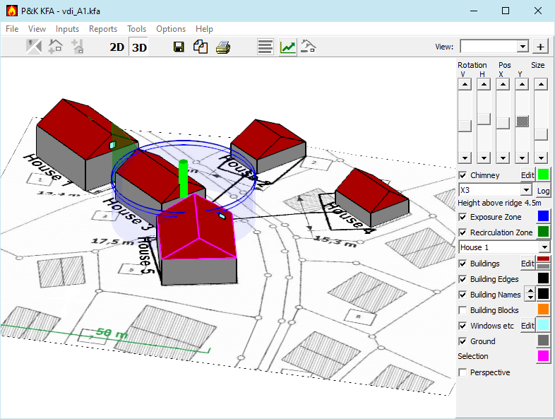
The terrain view is the central window of the program. This view can be a top view or to be a spatial representation.
The 3D view will usually be the basis for working with the program.
The top view serves mainly to place additional buildings.
Top View
Additional tools of the top view
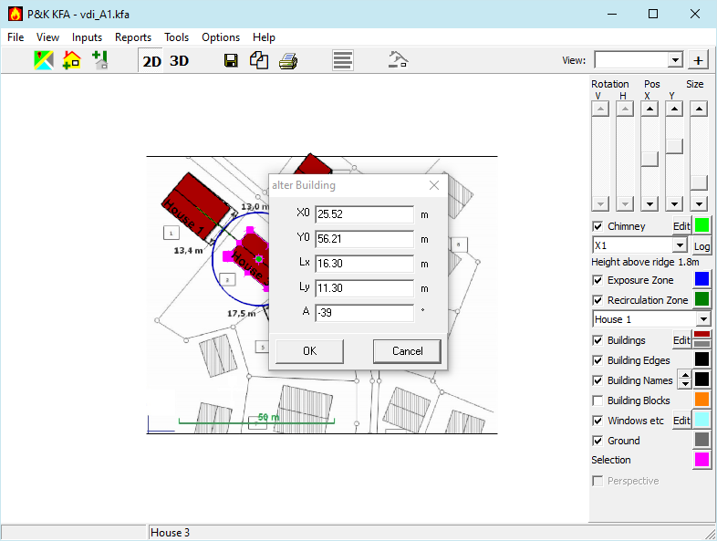
Edit Buildings
With a click on a house this can be selected. This is acknowledged by a frame with click marks. The lines through the marker points indicate in which direction the house can be modified. When dragging in such a direction, a window will appear showing the current outline data of the house. The data must be saved by pressing SAVE. The data can be changed manually before. The action is canceled by pressing Cancel or clicking in the void.
Edit Discharge Device (Chimney)
Clicking on a discharge device opens a dialog in which the attributes of these can be changed.
Measure
A click with the right mouse button and pressed CTRL key sets a reference position to which the angle and distance to the mouse position will be displayed in the status bar. Clicking with the right mouse button and holding down the ALT key or switching to 3D turns this function off again.
Rotation Center
Clicking with the left mouse button and holding down the CTRL key in the 2D view sets the rotation center for the 3D view.
 Import Map
Opens a dialog to import a map / background image).
 Add Building
Opens a dialog to add a building or structure on a selected building.
 Add Discharge Device (Chimney)
Opens a dialog to add a chimney to a selected building.
 Delete Buildings
A dialog to delete buildings incl. dependencies within or outside a selection rectangle. Useful if too many buildings have been imported.
 Show Hints
In case hints become available, this button blinks shortly and stays red. This avoids too many popups of the notification window.
 Simulation for building parameter (Expert Mode)
Opens a Form in which real values of a building can be varied and the course of the chimney height over ridge is illustrated.
Tools for both Views

 Change View
Changes view to 2D or 3D.
The key combination ALT-c resets the graphic position.
 Print
Print
The current image is transferred to Print Preview. When using an external browser, the preview has to be opened manuelly.
 Clipboard
The current image is copied to the clipboard for use in other programs. Right Click copies Logs.
 Save Graphic
The current image is saved as raster graphic. Right Click saves Logs.
View:  (store and recall)(Expert Mode)
For the documentation or while working, it can be helpful to access previous used views. In the combined input- and selection element one can store a named view + or recall > one. To update or delete a view use the right mouse button menu.
Operation in the right panel
Scrollbar and Mouse operation on the canvas
- Rotation V: Rotation around the horizontal axis
Equivalent to dragging the mouse with the left button pressed horizontally - Rotation H: Rotation around the vertical axis
Equivalent to dragging the mouse with the left button pressed vertically - Position X: Moving Horizontal
Equivalent to dragging the mouse with the right button pressed horizontally - Position Y: Moving vertical
Equivalent to dragging the mouse with the right button pressed vertically - Size: Scaling the Graphic
Equivalent to moving the mouse wheel
Chimney (Discharge Device)
- Checkbox: Controls visibility
- Edit: Opens Table of Discharge Devices
- Color: Allows Color change
- Combo: Selects Discharge device
- Log: Opens report of the calculation
Exposure Zone
- Checkbox: Controls visibility
- Color: Allows Color change
Recirculation Zone
- Checkbox: Controls visibility
- Color: Allows Color change
- Combo: Selects building with visualization of the Recirculation Zone
Buildings
- Checkbox: Controls visibility of the walls
- Edit: Opens Table of buildings
- Color: Allows changes of wall and roof color
Building Edges
- Checkbox: Controls visibility of edges
- Color: Allows Color change
Building Names
- Checkbox: Controls visibility of the names
- Color: Allows Color change
Note: In the 3D view, the names are shown on the Z0 level of the buildings. The names can look fragmented if the terrain rises next to the building. If it bothers, turn off the ground.
Building Blocks
- Checkbox: Controls visibility and consideration (see 3.5)
- Color: Allows Color change of block edges
Windows (Air Intakes / Ventilation Openings)
- Checkbox: Controls visibility
- Edit: Opens Table of Windows for interaction
- Color: Allows Color change
Ground
- Checkbox: Controls visibility
- Color: Allows Color change of the ground without background image
Perspective Othogonal (Expert Mode)
Default is orthogonal illustration, which is better for most tasks. If zoomed too far in, objects might be behind the eyes and therefore not vissible (clipped).
When Perspective is activated the graphic becomes perspective and can be zoomed more. Next to the checkbox appears a trackbar with which the angle of the perspective can be set. This helps if edges of objects are not properly stacked. This is a problem of 3D-libraries, which is called z-fighting.
3. Input Data
The Input menu contains access to the dialogs described below. Since discharge devices and supply air openings refer to buildings, it makes sense to first define the buildings.
If a site plan is available for the project, it should first be scanned to capture the building floor plans in 2D view.
3.1 Background Image / Map
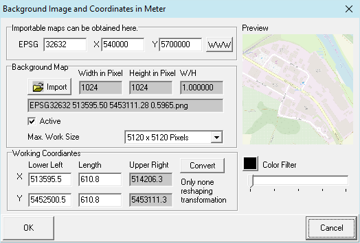
In this form, an image file can be defined as background. Files of the types gif, jpg, jpeg, tif, bmp, emf, wmf and png are usable, but preferably, a scalable format like emf or wmf should be used. The coordinates define the lower left and the expansion of the image. For files, which are accompanied by a coordinate reference file (world file, without rotation), these are read as well. The corresponding extensions are TGF, PGW, JGW or GFW.
Scaled PNG maps can be obtained via our Map Interface from www.openstreetmap.org. The necessary data for the scaling are contained in the file name, which therefore must not be changed.
Hint: Load image into a graphic program, rotate it, so it becomes horizontally aligned, then crop it to the above coordinates.
Supportet projections:
- EPSG:32631 = WGS 84 / UTM zone 31N
- EPSG:32632 = WGS 84 / UTM zone 32N
- EPSG:32633 = WGS 84 / UTM zone 33N
- EPSG:25831 = ETRS89 / UTM zone 31N
- EPSG:25832 = ETRS89 / UTM zone 32N
- EPSG:25833 = ETRS89 / UTM zone 33N
- EPSG:31467 = DHDN / 3-degree Gauss-Kruger zone 3
Coordinate System (optional): Complex coordinate transformations can be performed here. This feature may need to be installed separately.
Color Filter: With the slider one can make the image appear brighter and with the color button (when not black) a monochrome illustration can be obtained. This serves to unclutter other illustrations.
Max. Arbeitsgröße kann bei angeschalteten Expertenmode vergrößert werden. Damit wir die zu importierende Grafik, wenn größer, weniger verkleinert. Das erhöht die Qualität und vermindert die Performance vermindert.
Max. Work Size can be increased with Expert Mode enabled. Thereby the to be imported graphic will be less reduced in size (if greater). This will increase quality, but reduce perfomance.
Note: This form opens via click on  Import Map.
3.2 Buildings
Buildings as houses, factories, schools, stores and superstructures on buildings
3.2.1 Add Building
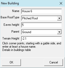
The first two marked corner points are interpreted as the gable side of the building. For a pent roof, it is the side with the roof edge rising to the right. These first gable marks are shown as ✖, all others appear as ✚. A click near an existing mark shifts it. A building with a symmetrical roof (pent roof rising to the right) and the specified eaves height will be generated. Further specification of the roof or other buildings is made in the list of buildings. If the pent roof should be rising to the left, the ridge position must be set to 0.
The terrain height can be set here. Its value is preset to the minimal terrain height.
Note: This form opens via click on Add Building.
3.2.2 Edit Buildings
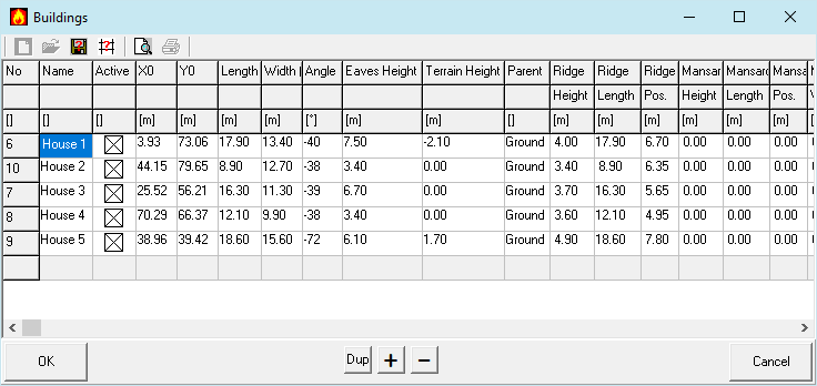
With this form the buildings are placed in a coordinate system. The coordinate system is created automatically or determined when adding a map. Buildings can also be comfortably added via the top view.
If this form was opened via the Edit button, selecting a building in the graphic will set the row accordingly. Contrariwise a click into a row will select or indicate the building in the graphic.
Name
Building names are indicated in reports and graphics and serve as references for discharge devices and supply air openings.
Active
Inactive buildings are ignored in calculation and display.
X0, Y0
The coordinates of the left lower vertex (anchor point) of the building in m.
Length (X)
Expansion of the gable side of the building in m. For flat roofs arbitrary
Width (Y)
Expansion of the building longitudinal side in m.
Angle
Rotation of building around the anchor point counterclockwise in degrees.
Eaves Height
Height of the building walls in m.
Terrain Height (Z0)
Height of the building base above the coordinate origin in m.
Parent
For roof superstructures: reference to the base building. Otherwise "ground".
Ridge Height
Height of the ridge above the eaves in m.
Ridge Length
Length of ridge in m. For saddle and pitch roofs it corresponds to the building length.
Ridge Position
Position of the ridge opposite the front building longitudinal side in m. For symmetrical roofs, it is half the building width.
Mansard Height
Height of the upper level of the mansard above the wall in m.
Mansard Length
Length of the upper edge of the mansard in m. In the case of a mansard roof, it corresponds to the building length.
Mansard Position
Position of the front upper edge of the mansard opposite the front longitudinal side of the building in m. For symmetrical roof, it is half the difference between building and mansard.
Mansard Width
Expansion of the upper edge of the mansard on the gable side in m.
Upper Opening Edge
For a simplified and more pessimistic analysis, a value greater than zero can be entered here. Any supply air openings in this building are then ignored and it is always assumed that there is an affected supply air opening with this height.
Label
This can be used to switch off the labels of individual buildings.
3.3 Discharge Devices
Discharge Devices are systems to channel off exaust gases or solvent fumes above roof. This includes chimneys, stacks, smokestacks, funnels, exhaust pipes etc.
3.3.1 Add/Edit Discharge Device
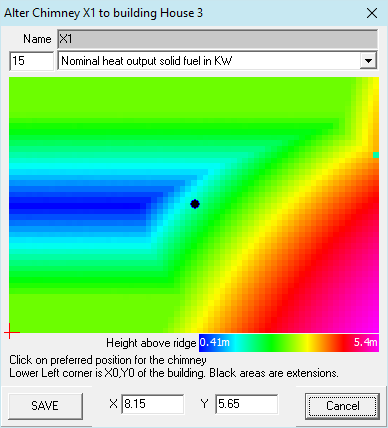
To the previously selected building, a location for the discharge device can be selected by clicking on the height distribution on the roof surface. Black areas represent extensions that can not be selected here.
Clicking on a discharge device opens this form and the attributes of the discharge device can be changed.
The Graphic will be updated in the background and can also be modified.
Height above ridge
Color scale of the expected height above ridge.
Name
Name of the discharge device for reports
X, Y
Position of discharge device on roof (visible after selection and editable)
+
Anchor point (X0, Y0) of building
Note: This form opens with a click on "Add Chimney to building" in der 2d-View.
Blocks
Takes for the block creation the dependency of the shimney location into account.
No longer switchable here, even thought its slow if block creation is on.
3.3.2 Edit Discharge Devices
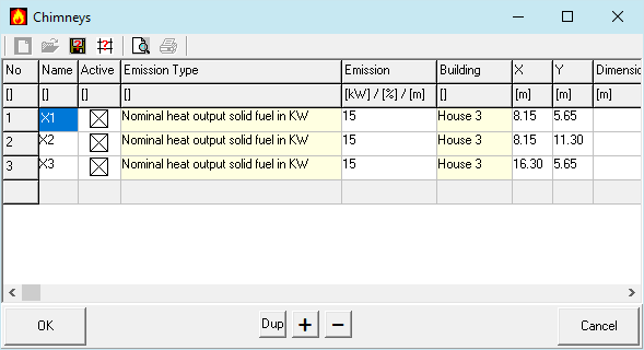
In this form the discharge devices are declared These can also be conveniently added or modified via "Add Discharge Device" in the 2D View.
Name
The names of the flue gas discharge devices are shown in the reports.
Active
Inactive exhaust discharge devices are ignored in calculations and illustrations.
Emission Type
Select one of:
- Oil and gas firing within the scope of the 1st BImSchV
- Firing with solid fuel within the scope of the 1st BImSchV
- Solvent according to 31. BImSchV
- Other Emissions: Exposure Zone
Emission
For combustion plants: nominal heat output in kW
For solvents: Percentage of the 31st BImSchV threshold.
For other Emissions: Radius of the Exposure Zone
Building
Reference to the building with the discharge device.
X
Position on the building in longitudinal direction in m.
Y
Position on the building in transverse direction in m.
Dimension
For the illustration only one can define the diameter or length and width (eg: 2 x 3) in m.
Emission of solvents
For calculations within the scope of the 31st BImSchV, the directive requires the following provisions:
- Section 5.2: For the additive term (HÜ) a height of 3 m
- Section 6.3.2: For the exposure area (R) a radius of 50 m
- Section 6.3.4: For the reference level (HB) a height of 5 m
- Section 6.3.1.2: A minimum height over terrain of 10 m
This definition applies to all parameters with the remark: For other than combustion plants outside the scope of application of the 31st BImSchV, the value may be graded in the same way as for the combustion plants accompanied.
Installations outside the 31st BImSchV fall below the emission threshold defined in this Ordinance.
P&K KFA integrates such systems by recording a percentage of the threshold value of the 31st BImSchV when emitting at such discharge devices. With this value, the relevant parameters are graded as follows:
- Additive Term (HÜ)
< 40%: 0,4 m
< 100%: 1 m
else 3 m - Exposure Area (R)
Share/2 m
maximal 50 m - Reference Level (HB)
≤ 21%: 1 m
≤ 26%: 2 m
≤ 36%: 3 m
≤ 55%: 4 m
else 5 m - Minimum Height (Equation 21)
≤ 21%: 2 m
≤ 26%: 4 m
≤ 36%: 6 m
≤ 55%: 8 m
else 10 m
Other Emissions
For the Emission type 'other emissionen' the radius of the exposure zone will be defined.
Dependent on this HÜ, HB and the minimal height will be determined as follows:
- Additive Term (HÜ)
< 20 m: 0,4 m
< 50 m: 1 m
else 3 m - Reference level (HB)
≤ 8 m: 1 m
≤ 10 m: 2 m
≤ 14 m: 3 m
≤ 22 m: 4 m
else 5 m - Minimal Height (Equation 21)
≤ 8 m: 2 m
≤ 10: 4 m
≤ 14: 6 m
≤ 22 m: 8 m
else 10 m
3.4 Edit Air Intakes (windows)
Air Intakes as ventilation openings, windows, doors, supply air openings where humans are staying.
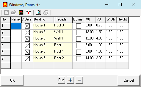
This dialog shows the table of all supply air openings, when opened vie the menu.
It is also possible to record air intake openings in interaction with the terrain view. For this purpose, this table is opened via the edit button of the Windows etc. in the terrain view. When opened via the edit button, the view is filtered.
Name
Building names are indicated in reports.
Active
Inactive buildings are ignored in calculation and display.
Building
Selected Building
Facade
Designation of the façade surface on which the supply air openings are located.
The areas are numbered around the building. The left gable side has the number 1. The other facade surfaces follow right around.
Dormer
A dormer is a supply air opening placed vertically on the roof surface.
X0
Position of the lower left corner of the supply air opening on the façade surface in m.
Y0
Height of the lower left corner of the supply air opening on the façade surface in m.
Width
Horizontal expansion of the supply air opening in m.
Height
Vertical expansion of the supply air opening in m.
3.5 Parameter
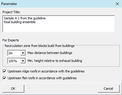
The form is used to define global settings for the project.
Project Title
The project title will be included in the output of graphics and reports.
Buildingblocks (Expert Mode)
The directive stipulates in chapter 6.2.2.2 the consideration of closed building groups when determining the recirculation zone of upstream buildings. P&K KFA integrates a general block analysis of the surrounding development.
The program automatically adds to the list of recirculation zones of the upstream buildings the recirculation zones of the virtual block buildings. These blocks will be generated from those buildings in the relevant neighborhood of the exhaust house, which meet the following criteria:
- The buildings must exceed a height: Default higher than half the height of the exhaust house.
- The distance between buildings must be below a minimum distance: Default less than 4m.
A block is a flat roof building that encloses all the buildings integrated into it. In addition to the recirculation zones of all individual buildings, blocks are also taken into account in the determination of the height of the exhaust gas discharge system.
The two criteria for blocking can be adjusted as follows:
- For the minimum height:
- Height is not relevant. All surrounding buildings are included
- same height as the exhaust house
- half height of the exhaust house
- third height of the exhaust house
- quarter height of the exhaust house
Recirculation zone according guideline
When calculating the recirculation zone, the guideline distinguishes between the route above the discharge building and the route outside the building. In two cases this leads to a discontinuity of the recirculation zone at the edge of upstream buildings.
1. Upstream ridge roofs
Above the building, the recirculation increases to the maximum height H2 and outside the building, the recirculation zone at the edge of the building always starts at the height H2. This then leads to a discontinuity at the edge of the building if the height H2 is only reached outside the building floor plan. Alternatively, P&K KFA offers the option of setting the starting height of the recirculation zone at the edge of the building to the value reached above the edge of the building.
2. Upstream flat roofs
For large flat roofs, the height of the discharge device may be reduced by two conditions formulated in Chapter 6.2.1.2.3. In order to avoid discontinuity at the edge, P&K KFA offers the possibility of also taking these conditions into account for the starting height of the recirculation zone at the edge of the building. Since equation 8 and the double building height refer to the height of the discharge device, both heights are reduced by the value HÜ. To this extent, the recirculation zone lies beneath the discharge device.
Two checkboxes under Inputs/Parameters offer the option of selecting the favoured procedure:
- Upstream flat roofs in accordance with the guideline (on) or deviating (off)
- Upstream ridge roofs in accordance with the guideline (on) or deviating (off)
The default is the option that complies with the guideline.
Note: The expert mode can be activated under Preferences.
3.6 CityGML Import
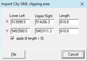
With this dialog buildings are imported from a file to be selected in the next step. Here one can define a section that is used to filter the CityGML file to import only a part of the buildings. If a background map was imported before this dialog, the corner coordinates are preset.
Buildings of tyoe LoD1 or LoD2 are considered.
3.7 CityGML Extract
(Expert Mode)
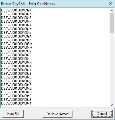
The CoreNames (defined in the CityGML file) can be used to extract parts from a larger CityGML file into a new file. The extract can possibly serve to simplify the examination of the data. The CoreNames can easily be found by importing a CityGML file and editing them in the graphical user interface. After the import, the CoreNames are located in the comment of the buildings. These can be copied in this form using the "Retrive Names" button. By pressing the File button you can enter the input file. The output file is then written out next to the input file with its name and the ending -extract.gml.
Note: The expert mode can be activated under Preferences.
4. Reports
4.1 Graphical Illustration
The graphical representations can be printed via the terrain view for use in the project documentation. The graphic is printed with current perspective and scaling.
4.2 Documentation of Results
The main menu Reports offers the possibility to output the details of the calculation paths and the results to printer or file. The sub-menu allows to choose input data or result tables, or both for output into a document. The tabular representations for the project documentation are initially submitted to a design tool.
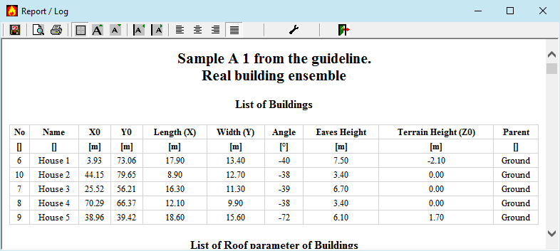
The Report Display is a HTML browser, which displays the results in a nice form. In the toolbar, there are buttons to save the report into a HTML file, to print the report, to toggle table borders, to size the font, to size cell padding, for the text alignmenti as well as  Choice of Elelements. In case the layout is to be modified with stylesheets, the form Options / Preferences is the place to look for.
 The preview button in the HTML view opens the HTML document in the standard browser, which is more suitable for printing long or complex documents.
Note: The settings made here will also be used in other HTML output (if possible). This is particularly important when using the default web browser, which can be selected in Preferences.
5. Operation
5.1 Within Forms
In the forms, the entries are made in form fields. With the keys Cursor up, Cursor down, Tab and Shift Tab or with the mouse the cursor can be moved over the fields. Cursor left and cursor right move the cursor character by character within a field.
Real numbers can be entered with a period or comma or as 1e-6 for 10-6. The error tone can be ignored on input, it is only triggered as a warning because 1e or 1e is not a valid number.
Possibly (if marked in the form) a selection list of discrete input values can be opened.
F1 provides context-sensitive help for a form field or the entire form and the integrated manual is accessible.
Click OK or CANCEL to leave the current form.
Also see: Calculator
5.2 Within Tables
The order and the width of all columns can be changed by clicking into a column header or between column headers and dragging as desired. This is practical if values are in a particular order, because Tab has to be pressed just once in order to reach the next column.
If the data in the columns are too wide to be displayed, then the symbols (in brackets) will be hidden in the column titles (e.g. Temperature (T0) ). Widening of the column will show that particular symbol.
The buttons "+" and "-" are used to insert or delete data sets. With the button "Dup" the current data set can be duplicated. The new row will become the last row in the table. This is useful if a data set is to be generated with minor difference to the current one. To insert a row, select the lower gray row before pressing the "+" button.
Individual fields, in which a selection is possible, are marked yellow. To activate the selection click once in a cell in order to select this; click a second time in order to activate the selection (no doubleclick).
With the cursor or Tab key, the focus can be moved between individual fields.
The illustrated section can be scrolled one row up or down by moving the cursor across the upper or lower edge of the table form.
Some tables can be sorted. With a right mouse button click into the considerable column, a Pull-Down Menu will be opened, and Sort Ascending or Sort Descending can be selected.
In some tables, a Row-Editor can be invoked. The Row-Editor shows one dataset only and can have more or less features then the grid dialog.
Sometimes single Columns can be imported via the Popup Menu. From the selected file, the values are taken and written to the position, from which the dialog was invoked. One value will be read per line from an ASCII file (includes CSV format) .
Table Import and Export
In the demo version the import is not available. Imports of non-base buildings must reference existing buildings!
In most tables, data can be imported or exported with the buttons in the tool bar. The sequence of the columns and which columns are used, depends on the current column order and the current filter setting. With a button in the tool bar, a form can be opened which gives information about the current settings.
Single Columns can be imported via the Popup Menu. From the selected file, the values are taken and written to the position, from which the dialog was invoked. One value will be read per line from an ASCII file (includes CSV format) .
Available formats for import and export
| CSV | Columns are separate by commas (Comma Separated Values). If a text contains commas, it must be written in " " (Quotation marks). The decimal character is the point. Values can optionally contain an exponent (e.g.: 6.E-9), however no additional separators are allowed. |
| TXT | Columns are separated by spaces. If a text contains spaces, it must be written in ' ' (Apostrophe). The decimal character is the point. Values can optionally contain an exponent (e.g.: 6.E-9), however no additional separators are allowed. |
| Current Project Extension | Individual tables can be loaded from project files. The loaded table must fit logically into the project. The export creates a new project file, which contains only the exported table. |
The formats can be selected in the appropriate dialogs under the type of file. The filter function is switched off for other formats than CSV, TXT and *!
Preview
The tables can be viewed in an appealing way using the HTML preview function. See here for report function.